The XEP1541 adaptor
Important notes
- You definitely need Schottky-diodes for this cable, the usual 1N4148 diodes don't work with most motherboards.
Construction
You need the following parts to build this adaptor:
- One printable circuit board of about 9 x 5.5 centimeters
- One PCB-mountable 6-pin DIN female port (Commodore serial port)
- One PCB-mountable 25-pin male plug (PC parallel plug)
- Four Schottky-diodes (e.g. 1N5819 or BAT85)
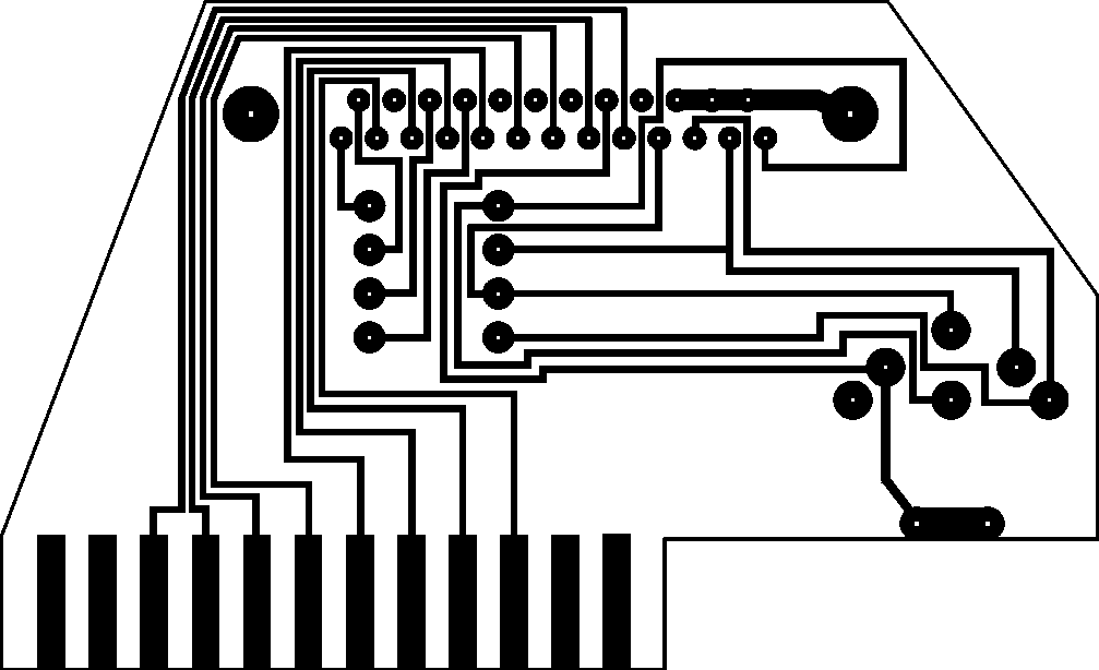
Step 1. Build the board of the adaptor, cut it to shape and drill the holes in it, based on the board diagram (300 DPI resolution). This diagram shows the board as viewed from below.
Step 2. Solder the PCB-mountable DIN port and parallel plug onto the upper side of the board.
Step 3. Build the diode bridges between the appropriate pins of the parallel plug on the upper side of the board. These include the following connections:
| Parallel plug | Parallel plug |
|---|---|
| 13, SelectIn | 1, Strobe |
| 12, PaperEnd | 14, AutoFeed |
| 11, Busy | 17, Select |
| 10, Ack | 16, Init |
The cathodes should be pointing towards the pins in the right column of the table, which corresponds to the right when the adaptor is viewed from its back side, where the DIN port and the user port edge are.
The parts should be soldered the following way onto the board. This diagram shows the board as viewed from above. Note the small band on the right side of the diodes.
![[XEP1541 adaptor]](images/xep1541ap.gif)
Circuit diagram:
![[XEP1541 adaptor]](images/xep1541ac.gif)
You can find the description of all parts used on the diagrams at the legend page.
Source: The Joe Forster-STA homepage
[Back]