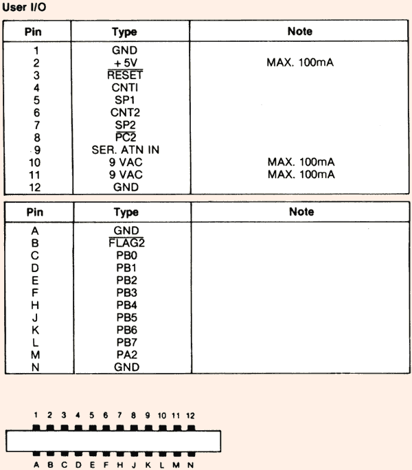
Commodore 64 / 128 User I/O

24 pin male edge (DZM 12 DREH) at the computer.
|
Top side |
||
|---|---|---|
| 1 | GND | Ground |
| 2 | +5VDC | (100 mA max) |
| 3 | /RESET | Reset, will force a Cold Start. Also a reset output for devices. |
| 4 | CNT1 | Serial port counter from CIA #1 |
| 5 | SP1 | Serial port from CIA #1 |
| 6 | CNT2 | Serial port counter from CIA #2 |
| 7 | SP2 | Serial port from CIA #2 |
| 8 | /PC2 | Handshaking line from CIA #2 |
| 9 | ATN | This pin is connected to the ATN line of the serial bus |
| 10 | +9VAC | (+ phase) Connected directly to the Commodore 64 transformer (100 mA max) |
| 11 | +9VAC | (- phase) Connected directly to the Commodore 64 transformer (100 mA max) |
| 12 | GND | Ground |
|
Bottom side |
||
| A | GND | Ground |
| B | /FLAG2 | The Commodore 64 gives you complete control over Port B on VIA chip #1. Eight lines for input or output are available, as well as 2 lines for handshaking with an outside device. The I/O lines for Port B are controlled by two locations. One is the port itself, and is located at 56577 ($DD01 hex). Naturally you PEEK it to read an input, or POKE it to set an output. Each of the eight I/O lines can be set up as either an input or an output by setting the data direction register properly. It is located at 56579 ($DD03 hex). |
| C | PB0 | |
| D | PB1 | |
| E | PB2 | |
| F | PB3 | |
| H | PB4 | |
| J | PB5 | |
| K | PB6 | |
| L | PB7 | |
| M | PA2 | |
| N | GND | Ground |
Source: Commodore 64 User Manual, Commodore 64 Programmer's Reference Guide
[Back]