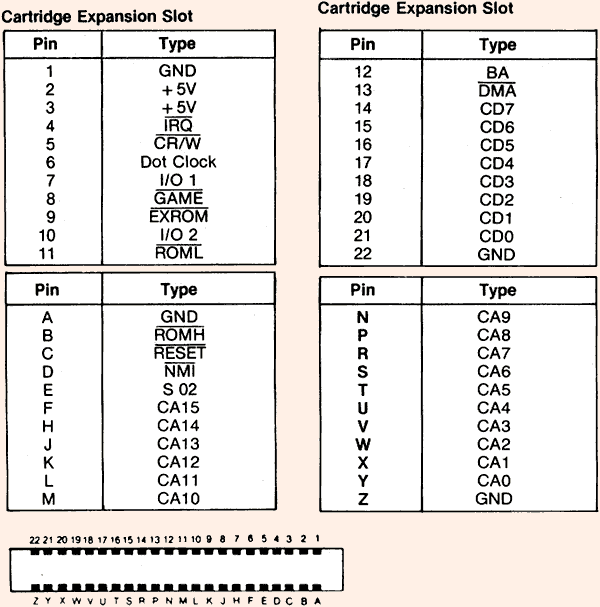
Commodore 64 / 128 Cartridge Slot

44 pin female edge at the computer. The pins function as described below:
| Top | ||
| 1 | GND | System ground. All four ground lines are usually tied together. |
| 2,3 | +5VDC | 5-volt power supply to the cartridge. (Total user port and cartridge devices can draw no more than 450 mA.) |
| 4 | /IRQ | IRQ. As long as this is low, it requests an interrupt. |
| 5 | R/W | Read/write line. Reads when low, writes when high. |
| 6 | DOT CLOCK | 8.18 MHz video dot clock input, for your own video control. |
| 7 | /I/O1 | I/O 1 goes low when 64 detects use of $DE00-$DEFF; can be used with CP/M. |
| 8 | /GAME | GAME replaces BASIC ROM with external cartridge ROM when grounded. |
| 9 | /EXROM | EXROM replaces RAM $8000-$9FFF with cartridge ROM when grounded. |
| 10 | /IO2 | I/O 2 goes low when 64 detects use of $DF00-DFFF. |
| 11 | /ROML | ROML chip enable selects ROM $8000-$9FFF when EXROM is low; needs address bits A0-A12. |
| 12 | BA | Bus available signal from the VIC-II chip. To use, pull DMA low. An external device can control the 64 while BA is high. |
| 13 | /DMA | Direct memory access request line. |
| 14-21 | D7-0 | D7 through D0. The data bus carries eight bits of data. |
| 22 | GND | System ground |
| Bottom | ||
| A | GND | System ground |
| B | /ROMH | ROMH selects external ROM at $A000-$BFFF (or $E000-$EFFF, for MAX) when GAME or EXROM is low; needs address bits A0-A12. |
| C | /RESET | RESET detects a positive voltage, resetting when rising from ground to +5 volts. |
| D | /NMI | NMI connects to 6510 Non-Maskable Interrupt line. It is spike sensitive - needs a pulse in either direction. Normally high, so many devices can signal NMI. |
| E | S02 | Phase 2 system clock. Essential for I/O timing, but not necessary for external ROM. |
| F-Y | A15-0 | Address bus (A15 - A0). The full 16 address lines are necessary for DMA. |
| Z | GND | System ground |
Source: Commodore 64 User Manual, Programming the Commodore 64, Commodore 64 Programmer's Reference Guide
[Back]